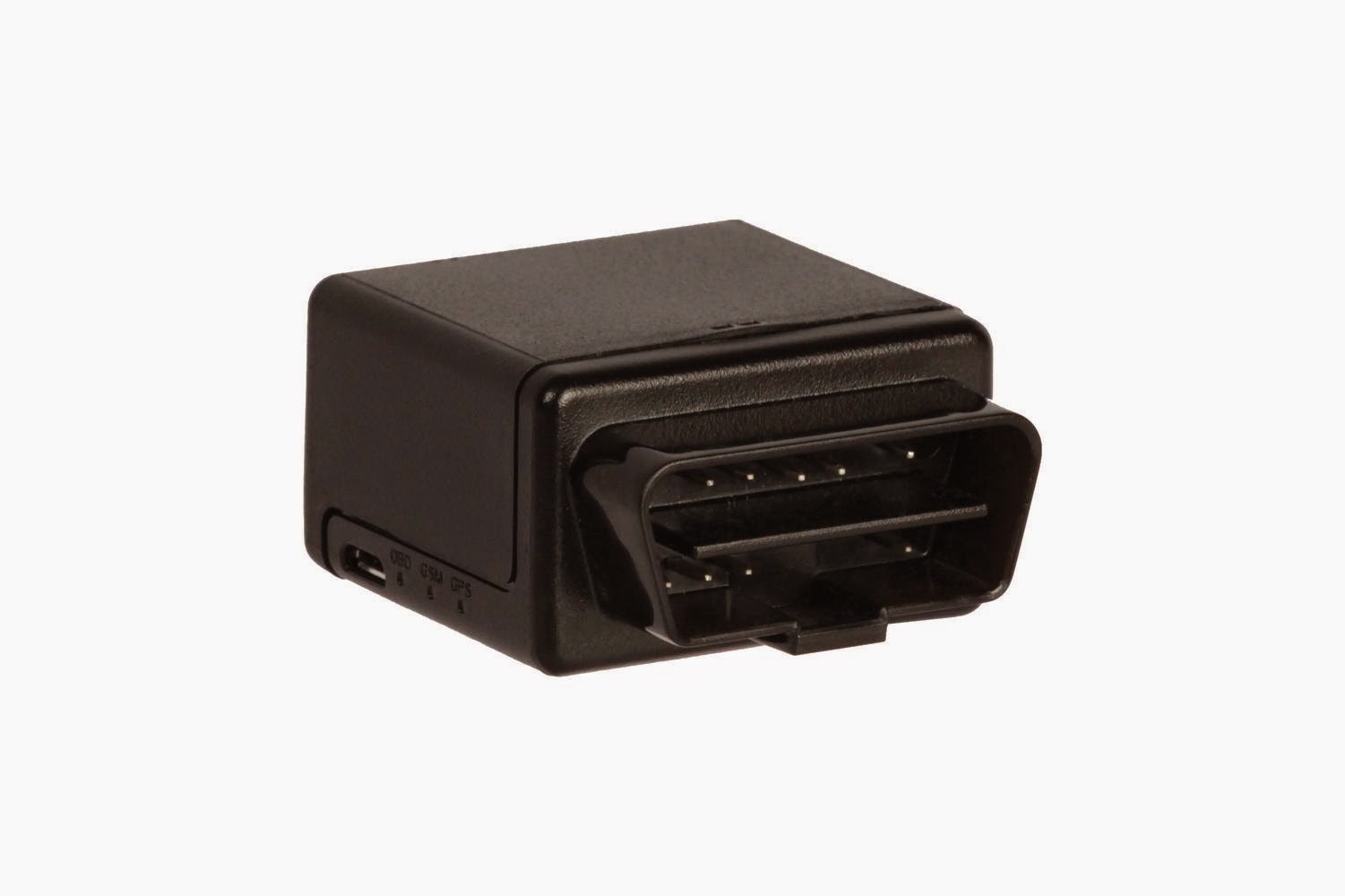
On-board diagnostics (OBD) is an automotive term referring to a vehicle's self-diagnostic and reporting capability. OBD systems give the vehicle owner or repair technician access to the status of the various vehicle subsystems. Modern OBD implementations use a standardized digital communications port to provide real-time data in addition to a standardized series of diagnostic trouble codes, or DTCs, which allow one to rapidly identify and remedy malfunctions within the vehicle
OBD II Signal Protocol:
There are five signaling protocols that are permitted with the OBD-II interface. Most vehicles implement only one of the protocols. It is often possible to deduce the protocol used based on which pins are present on the J1962 connector:
- SAE J1850 PWM (pulse-width modulation — 41.6 kB/s, standard of the Ford Motor Company)
- pin 2: Bus+
- pin 10: Bus–
- High voltage is +5 V
- Message length is restricted to 12 bytes, including CRC
- Employs a multi-master arbitration scheme called 'Carrier Sense Multiple Access with Non-Destructive Arbitration' (CSMA/NDA)
- 2. SAE J1850 VPW (variable pulse width — 10.4/41.6 kB/s, standard of General Motors)
- pin 2: Bus+
- Bus idles low
- High voltage is +7 V
- Decision point is +3.5 V
- Message length is restricted to 12 bytes, including CRC
- Employs CSMA/NDA
- ISO 9141-2. This protocol has an asynchronous serial data rate of 10.4 kbit/s. It is somewhat similar to RS-232; however, the signal levels are different, and communications happens on a single, bidirectional line without additional handshake signals. ISO 9141-2 is primarily used in Chrysler, European, and Asian vehicles.
- pin 7: K-line
- pin 15: L-line (optional)
- UART signaling
- K-line idles high, with a 510 ohm resistor to Vbatt
- The active/dominant state is driven low with an open-collector driver.
- Message length is Max 260Bytes. Data field MAX 255.
- ISO 14230 KWP2000 (Keyword Protocol 2000)
- pin 7: K-line
- pin 15: L-line (optional)
- Physical layer identical to ISO 9141-2
- Data rate 1.2 to 10.4 kbit/s
- Message may contain up to 255 bytes in the data field
- ISO 15765 CAN (250 kbit/s or 500 kbit/s). The CAN protocol was developed by Bosch for automotive and industrial control. Unlike other OBD protocols, variants are widely used outside of the automotive industry. While it did not meet the OBD-II requirements for U.S. vehicles prior to 2003, as of 2008 all vehicles sold in the US are required to implement CAN as one of their signaling protocols.
- pin 6: CAN High
- pin 14: CAN Low
SAE standards documents on OBD-II:
- J1962 - Defines the physical connector used for the OBD-II interface.
- J1850 - Defines a serial data protocol. There are two variants- 10.4 kbit/s (single wire, VPW) and 41.6 kbit/s (two wire, PWM). Mainly used by US manufacturers, also known as PCI (Chrysler, 10.4 kbit/s), Class 2 (GM, 10.4 kbit/s), and SCP (Ford, 41.6 kbit/s)
- J1978 - Defines minimal operating standards for OBD-II scan tools
- J1979 - Defines standards for diagnostic test modes
- J2012 - Defines standards trouble codes and definitions.
- J2178-1 - Defines standards for network message header formats and physical address assignments
- J2178-2 - Gives data parameter definitions
- J2178-3 - Defines standards for network message frame IDs for single byte headers
- J2178-4 - Defines standards for network messages with three byte headers*
- J2284-3 - Defines 500 kbit/s CAN Physical and Data link layer
- J2411 - Describes the GMLAN (single-wire CAN) protocol, used in newer GM vehicles. Often accessible on the OBD connector as PIN 1 on newer GM vehicles.
SAE standards documents on HD (heavy duty) OBD:
- J1939 - Defines a data protocol for heavy duty commercial vehicles
ISO standards
- ISO 9141: Road vehicles — Diagnostic systems. International Organization for Standardization, 1989.
- Part 1: Requirements for interchange of digital information
- Part 2: CARB requirements for interchange of digital information
- Part 3: Verification of the communication between vehicle and OBD II scan tool
- ISO 11898: Road vehicles — Controller area network (CAN). International Organization for Standardization, 2003.
- Part 1: Data link layer and physical signalling
- Part 2: High-speed medium access unit
- Part 3: Low-speed, fault-tolerant, medium-dependent interface
- Part 4: Time-triggered communication
- ISO 14230: Road vehicles — Diagnostic systems — Keyword Protocol 2000, International Organization for Standardization, 1999.
- Part 1: Physical layer
- Part 2: Data link layer
- Part 3: Application layer
- Part 4: Requirements for emission-related systems
- ISO 14320 no data
- ISO 15031: Communication between vehicle and external equipment for emissions-related diagnostics, International Organization for Standardization, 2010.
- Part 1: General information and use case definition
- Part 2: Guidance on terms, definitions, abbreviations and acronyms
- Part 3: Diagnostic connector and related electrical circuits, specification and use
- Part 4: External test equipment
- Part 5: Emissions-related diagnostic services
- Part 6: Diagnostic trouble code definitions
- Part 7: Data link security
- ISO 15765: Road vehicles — Diagnostics on Controller Area Networks (CAN). International Organization for Standardization, 2004.
- Part 1: General information
- Part 2: Network layer services ISO 15765-2
- Part 3: Implementation of unified diagnostic services (UDS on CAN)
- Part 4: Requirements for emissions-related systems
http://en.wikipedia.org/wiki/On-board_diagnostics
http://en.wikipedia.org/wiki/OBD-II_PIDs


